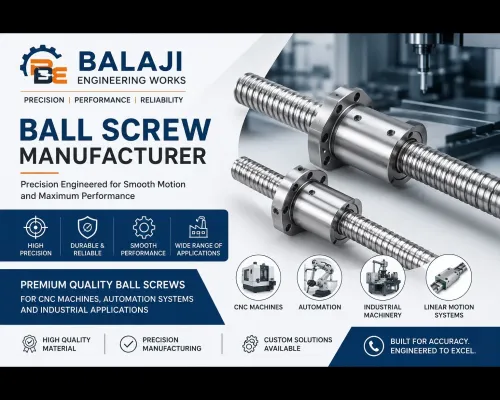

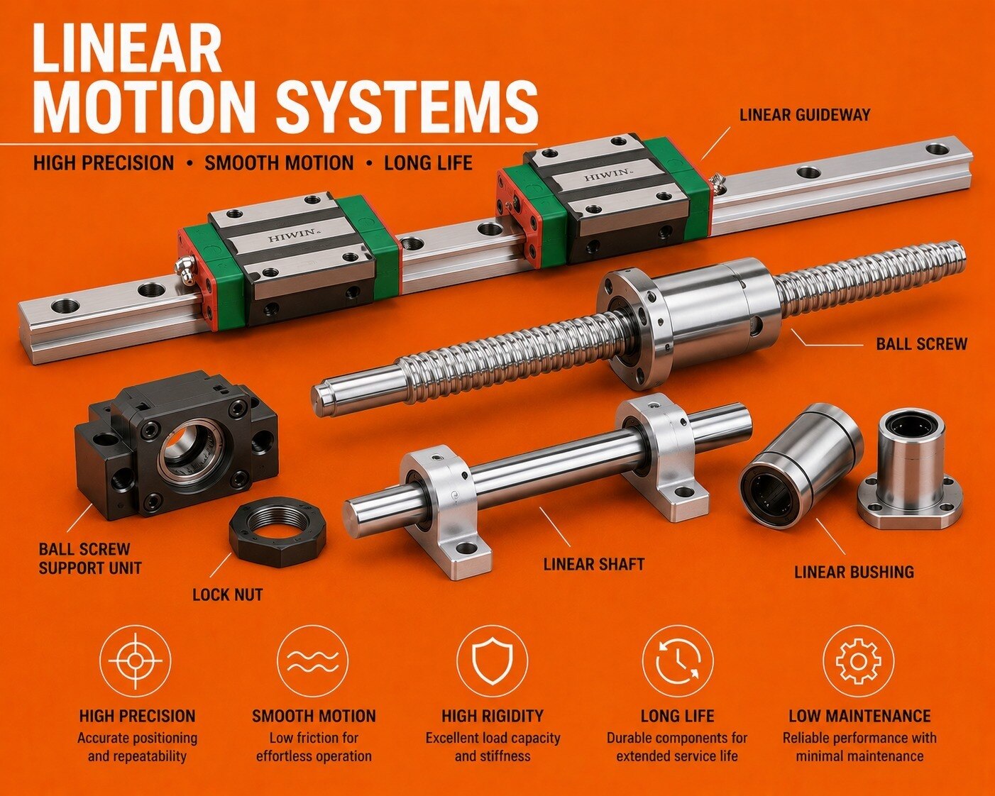
Unstable machine travel can come from backlash, stick-slip, rail binding, shaft runout, structural deflection, thermal growth, or a servo fault. You will learn how to separate those causes, record the measurements a replacement supplier needs, and specify an axis that remains stable under its real load and speed.
Key takeaways
- Measure backlash, straightness, repeatability, and load-dependent error before replacing parts.
- Trace faults through the carriage, rail, screw, coupling, motor, encoder, and control loop.
- Match the replacement to the failure: guide, screw, coupling, bearing, or complete motion system.
- Require alignment records, preload details, lubrication instructions, and acceptance-test results from the supplier.
Define the travel error before replacing a part
Unstable machine travel means the carriage does not follow the commanded path with consistent position, speed, or resistance. It may show backlash, stick-slip, vibration, axis wander, uneven resistance, rail deflection, or position error under load.
Do not replace a guide or ballscrew until you separate those symptoms with measurements; a dial indicator at one point cannot prove full-axis performance.
| Symptom | Measurement | What it points toward |
|---|---|---|
| Poor bidirectional accuracy | ISO 230-2 positioning test in both directions | Scale, pitch, thermal, or control compensation error |
| Poor unidirectional repeatability | Repeated approaches from one direction | Guide friction, contamination, preload, or servo instability |
| Lost motion on reversal | Reversal error or backlash measurement | Worn nut, coupling, rack, belt, or loose mounting |
| Stick-slip or velocity ripple | Low-speed trace with motor-current record | Lubrication, excessive preload, bearing damage, or drive tuning |
| Straightness or axis wander | Indicator sweep or laser interferometer over full stroke | Shaft runout, rail alignment, frame distortion, or deflection |
Record the conditions that make the error appear before choosing an unstable linear travel solution:
- Travel length, carriage load, moment load, speed, acceleration, duty cycle, and operating temperature
- Repeatability, reversal error, straightness, allowable deflection, and error under the working load
- Shaft diameter, rail size, mounting-hole pattern, lubrication condition, and contamination exposure
Increasing preload can reduce clearance while increasing friction, torque, heat, and alignment sensitivity. The highest preload is not automatically the correct replacement. A credible test specification states warm-up time, load state, test speed, measurement method, full travel range, bidirectional accuracy, repeatability, straightness, and reversal error.
Trace the fault from the carriage to the control loop
Start with the drive disconnected and move the carriage through its full stroke by hand. A tight spot, changing effort, or stick-slip points to the guide, shaft-and-bush assembly, contamination, seal drag, or excessive preload before you investigate the servo.
Record the fault at several positions, speeds, and loads. Then isolate each layer in this order:
1. Inspect the guide and carriage for contamination, damaged raceways, loose mounting bolts, and uneven preload. A force spike that repeats at one location indicates guide geometry or local damage.
2. Check a supported shaft with a dial indicator while rotating it. Excessive runout, a worn bush, or a bent shaft produces position variation that follows shaft rotation rather than commanded motion.
3. Reverse the ballscrew slowly and measure lost motion. Separate screw-nut backlash from coupling wind-up, bearing clearance, and mount looseness; a zero-backlash nut cannot correct guide binding or frame deflection.
4. Compare commanded position, encoder position, following error, motor current, and vibration during acceleration and constant-speed travel. Error that changes with speed points toward friction, resonance, tuning, or drive compliance.
5. Test the encoder and its coupling against an independent indicator or laser measurement. If the controller reports stable feedback while the carriage moves incorrectly, inspect encoder mounting, scale contamination, coupling slip, and feedback wiring.
6. Measure frame straightness, rail parallelism, and carriage deflection under load. Movement that changes when mounting bolts are loosened or the workpiece load shifts belongs to the machine structure, not the ballscrew alone.
A fault that survives mechanical isolation belongs in the control loop; a fault that remains with power removed belongs in the axis mechanics or frame.
Match the replacement architecture to the failure
Match the replacement to the measured failure, not to the part that looks worn. A bearing or bush is enough when clearance, noise, or stick-slip is confined to one carriage and the shaft is straight, smooth, and correctly aligned. Choose a larger intervention when the error remains after the isolated defect is removed.
| Option | What it means | When it applies |
|---|---|---|
| Bearing or bush | Replace the sliding or rolling element | The shaft has no scoring or runout, mounting seats are sound, and the fault follows one bearing or bush |
| Shaft | Replace the guide shaft and retain the basic architecture | The shaft is bent, worn, undersized, or permanently grooved while the supports and load remain suitable |
| Profiled rails | Convert to matched rail-and-carriage guides | Shaft deflection, low stiffness, or poor straightness causes travel error under payload or cutting force |
| Second rail | Add parallel support and additional carriages | One rail twists, the carriage yaws, or the applied moment exceeds the existing guide’s capacity |
| Complete axis | Replace guide, screw or actuator, drive, feedback, and interfaces | Errors combine across the mechanics and control loop, or the frame cannot hold alignment |
Do not call parts interchangeable because rail width or shaft diameter matches. Verify preload, accuracy class, carriage length, hole pattern, reference side, seals, lubrication, allowable moment, and screw critical speed.
An industrial motion system replacement also needs stroke, payload centre of gravity, speed, acceleration, duty cycle, environment, motor, encoder, and interface drawings; otherwise, a dimensional match can produce the same unstable travel.
Control alignment, preload, lubrication, and acceptance testing
Reliable full-stroke travel depends on installation geometry as much as on the replacement component. A guide installed against a twisted mounting face will bind at one end, while excessive preload increases friction, drive torque, heat, and sensitivity to misalignment.
Control the installation with a documented procedure:
- Clean the mounting faces, stone raised burrs, and measure straightness before tightening.
- Align the guide, shaft, or screw to the machine datum; tighten in sequence while checking carriage resistance.
- Select preload for the required rigidity and load, not the highest available grade.
- Apply the specified lubricant in the correct quantity, then cycle the axis slowly before testing.
- Check coupling alignment, bearing seating, bolt torque, and encoder mounting after assembly.
A single dial-indicator reading near the home position cannot prove full-axis performance. Define an acceptance test before approving the replacement, including stroke, load state, warm-up time, test speed, and measurement locations. Record bidirectional positioning accuracy, repeatability, straightness, and backlash or reversal error at several positions across the travel.
Use ISO 230-2 methods to separate positioning accuracy from repeatability by direction. Use laser interferometry when you need a defensible positioning-error map over the complete stroke. Repeat the test at operating temperature; a cold axis can pass while thermal growth later creates end-of-travel error.
Reject “smooth travel” as a specification unless the measured limits and test conditions are written down.
Choose a supplier that can prove the corrected result
Require a documented diagnostic, installation, and acceptance package before approving the replacement—not merely a component quotation. Calling a firm a linear motion systems manufacturer in Hyderabad proves its location and category, not its ability to correct unstable travel.
A linear motion systems manufacturer for unstable machine travel in Hyderabad should provide:
- A sizing record covering stroke, payload and centre of gravity, orientation, speed, acceleration, duty cycle, process forces, temperature, contamination, lubrication, motor, feedback, and interface drawings.
- A failure report identifying the dominant error as geometric, mechanical, thermal, lubrication-related, or servo-related.
- A selection drawing naming the guide or bush, shaft or ballscrew, preload, coupling, motor, and encoder arrangement.
- An alignment procedure stating mounting-surface flatness, rail parallelism, height control, bolt-tightening sequence, and inspection tools.
- A signed acceptance report with raw measurements before and after installation.
Use this comparison when reviewing the supplier’s proof:
| Evidence | Acceptable proof | Approval meaning |
|---|---|---|
| Nominal component match | Size, hole pattern, and load rating only | Reject; it does not prove stable travel |
| Installation proposal | Alignment tolerances, preload setting, and tightening sequence | Proceed to technical review |
| Corrected-result test | Travel range, warm-up, speed, load, bidirectional accuracy, repeatability, straightness, and reversal error | Approve only if values meet your specification |
Give the same checklist to any machine motion supplier in Hyderabad. If Balaji Engineering Works is being considered, request these records before treating its linear guide or motion-system selection as a completed replacement.
Related products
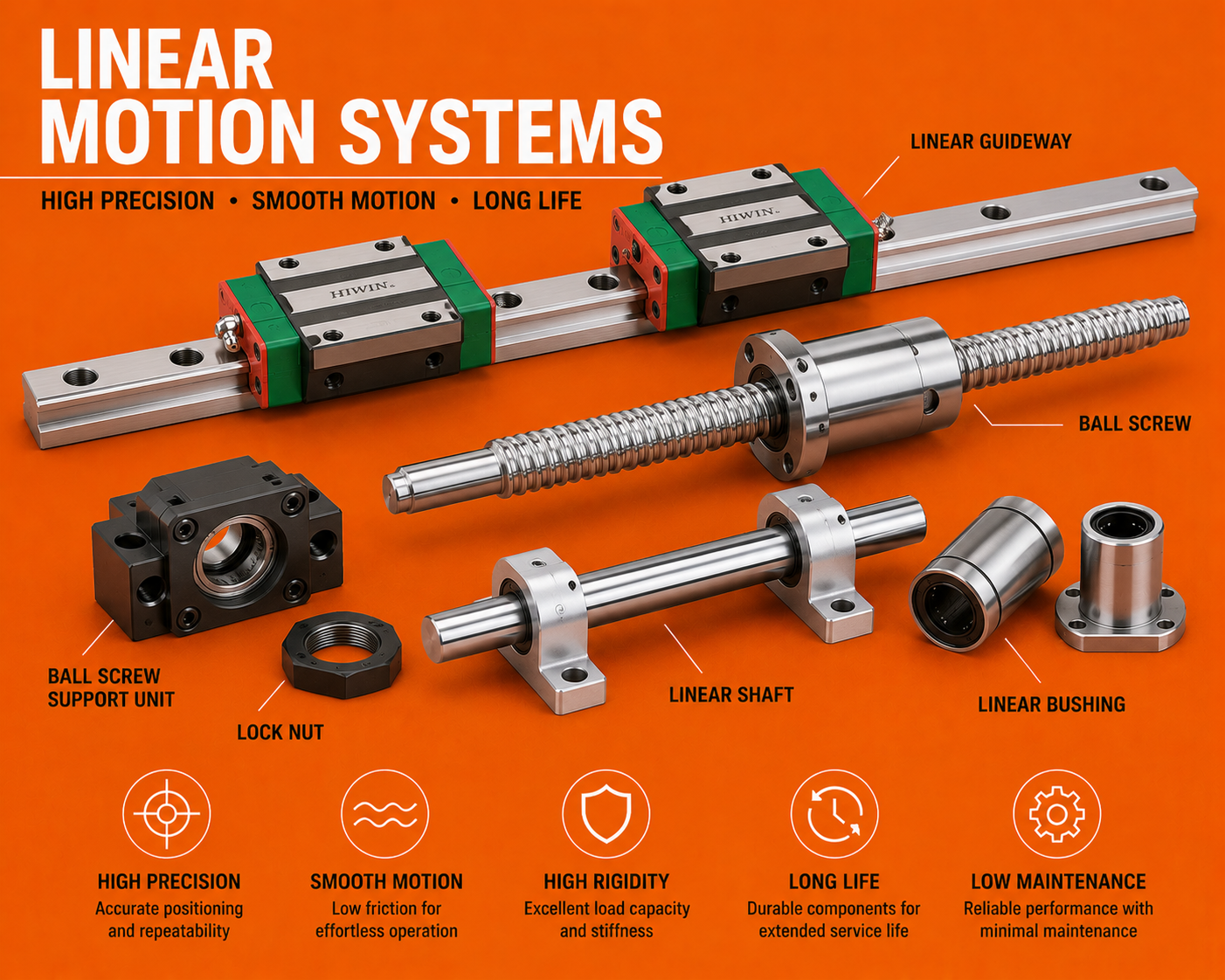 | Linear Motion Product Overview Balaji Engineering Works offers advanced Linear Motion Systems designed to deliver smooth, accurate, and efficient linear movement... View product → |
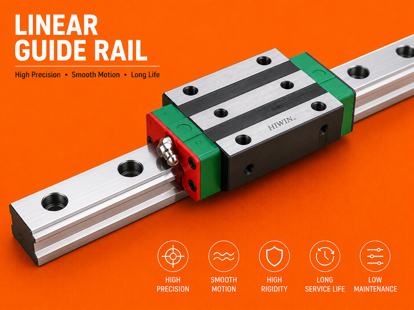 | Linear Motion Guideways Balaji Engineering Works is a trusted supplier of Linear Guide Rails in Pune, designed to provide accurate, smooth, and stable linear motion for... View product → |
Frequently asked questions
How do you define unstable machine travel before replacing a part?
Measure backlash, repeatability, straightness, speed variation, vibration, resistance, and position error under the actual load. Record whether the error changes with direction, speed, temperature, or travel position.
How can you trace a travel fault from the carriage to the control loop?
Inspect the carriage, guideways, ballscrew or belt, coupling, bearings, motor, encoder, and servo settings in sequence. Compare mechanical measurements with commanded position, feedback position, following error, and drive alarms.
How do you match a replacement architecture to the failure?
Replace the failed guide, screw, bearing, coupling, or encoder when the rest of the axis remains accurate. Choose a complete industrial motion system replacement when wear, misalignment, stiffness, and control compatibility affect several elements.
What must you control during installation and acceptance testing?
Control rail alignment, mounting-surface condition, preload, lubrication type and quantity, coupling alignment, torque, and thermal effects. Test repeatability, backlash, straightness, speed stability, and loaded positioning against recorded limits.
What should a motion-system supplier prove before you approve the corrected result?
Ask for component specifications, fit and tolerance details, alignment records, preload data, lubrication instructions, inspection measurements, and signed acceptance-test results. A supplier such as Balaji Engineering Works should connect those records to your machine's measured fault.
Related products
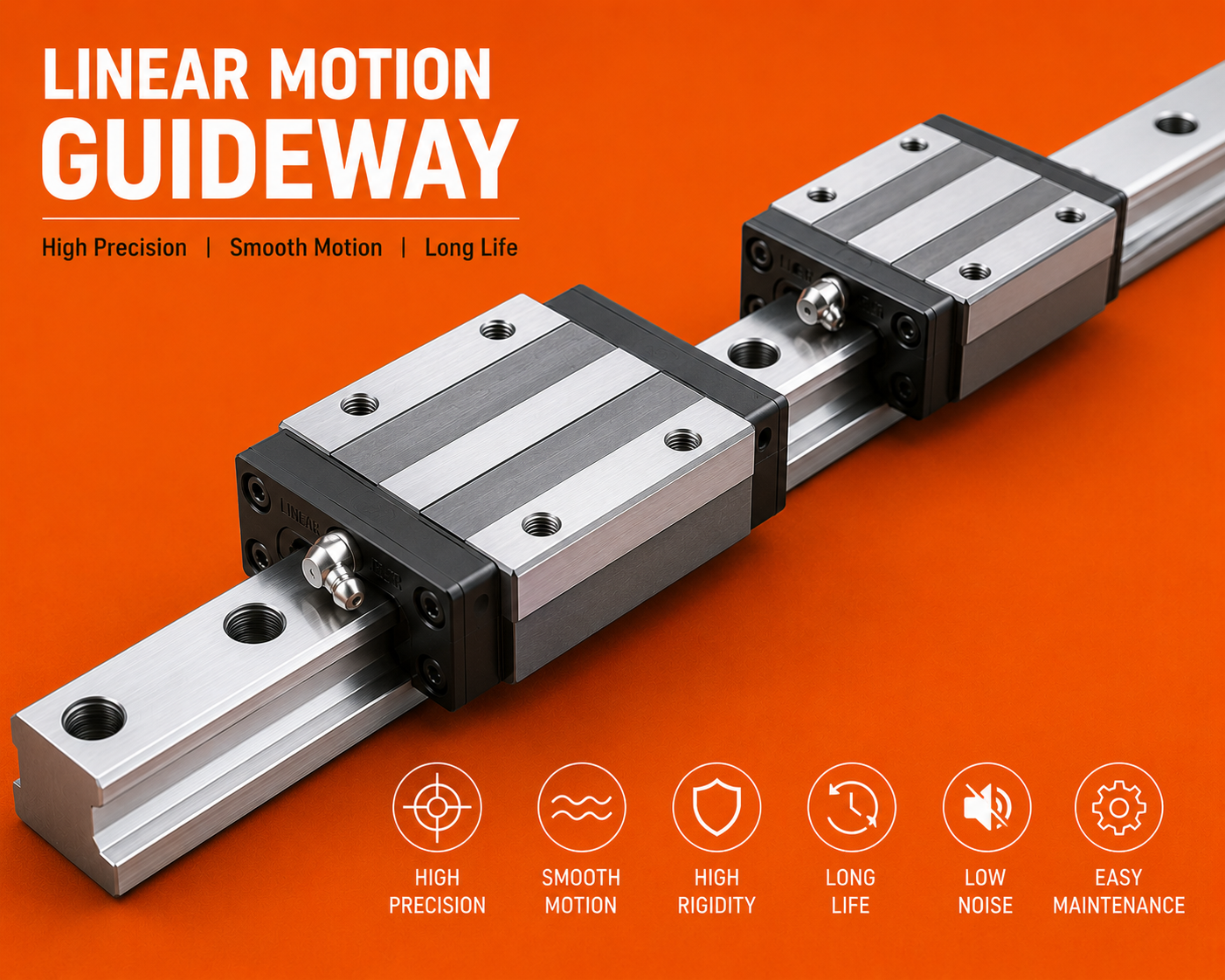 | Linear Motion Guideways Balaji Engineering Works offers high-performance Linear Motion Guideways in Pune, designed to ensure smooth, precise, and efficient linear movement... View product → |
 | Linear Bearing Balaji Engineering Works is a trusted manufacturer and supplier of Linear Motion Bushes in Pune, designed for smooth, precise, and low-friction... View product → |
 | Linear Bearing Flange Type Linear Motion Bearing Balaji Engineering Works offers high-quality Flange Type Linear Motion Bearings in Pune, designed for smooth, accurate, and stable linear motion in... View product → |
 | Linear Bearing Balaji Engineering Works is a trusted supplier of Linear Ball Bearings in Pune, designed to provide smooth, precise, and low-friction linear motion... View product → |