
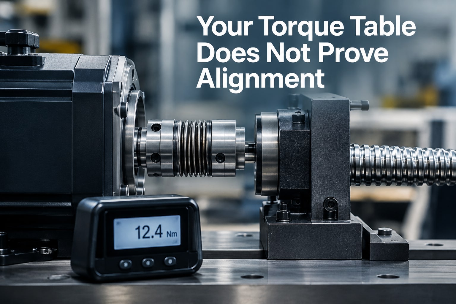
A motor shaft coupling is a function, not one specific coupling design, so the useful comparison depends on whether the alternative uses an elastomeric jaw, Oldham, beam, disc, or rigid element. By the end, you will be able to match the coupling to your shaft offsets, torque cycle, speed, installation accuracy, and service environment instead of relying on a generic claim that it accommodates misalignment.
Key takeaways
- Define the coupling type before comparing motor shaft alignment capacity.
- Match misalignment, torque, speed, and motion duty—not torque alone.
- Install shafts within limits without forcing or loading the bellows.
- Request test data, balancing details, and fatigue evidence from the supplier.
First identify what “motor shaft coupling” means in the comparison
“Motor shaft coupling” names the job, not one coupling design. It means the device joining a motor shaft to a driven shaft, so an industrial bellows coupling comparison must identify the competing mechanism: bellows, jaw, beam, Oldham, disc, or rigid.
| Design | Flexible element | Alignment behaviour | Main consequence |
|---|---|---|---|
| Industrial bellows coupling | Thin-wall stainless-steel bellows | Very low parallel offset; limited angular and axial movement | Zero backlash and high torsional stiffness, but excessive offset rapidly shortens bellows fatigue life |
| Elastomeric jaw coupling | Spider insert between jaws | Good damping and greater misalignment tolerance | Handles shock well, but the elastomer adds torsional wind-up and can wear |
| Oldham coupling | Sliding centre disc | High parallel-offset capacity | Accommodates offset, but the disc and slots introduce wear and backlash |
| Beam or disc coupling | Machined beams or metal discs | Angular and axial flexibility; parallel capacity depends on design | Compact and precise, but each design has a defined fatigue and displacement limit |
| Rigid coupling | Solid sleeve or flange | No intentional compensation | Only suitable after the shafts are aligned accurately |
A stainless-steel bellows is not automatically an electrical insulator; its metal path normally conducts between shafts. Specify an insulating element or isolating hub arrangement when electrical separation is required. For high-speed service, check balance grade, hub concentricity, bore runout, clamping method, key or set-screw effects, and the assembled system’s critical speed.
Never use a bellows coupling to pull misaligned shafts together.
Compare alignment capacity with the actual torque and motion duty
Match the coupling’s allowable angular, axial, and parallel misalignment to the measured shaft condition; do not select by motor power alone. Compare rated torque, peak or reversing torque, torsional stiffness, maximum speed, bore and keyway dimensions, axial movement, temperature, corrosion exposure, and required service life.
| Option | Alignment and motion behaviour | Duty specifications to verify |
|---|---|---|
| Industrial bellows coupling | High torsional stiffness with angular and axial compliance; limited parallel-offset capacity | Rated and peak torque, torque per angular displacement, speed, bore, clamp range, allowable misalignment, fatigue life, temperature, and corrosion resistance |
| Elastomeric jaw coupling | Greater shock and installation-error tolerance, but the insert adds compliance and can deteriorate | Continuous and peak torque, insert hardness, speed, temperature, service factor, and replacement life |
| Disc coupling | Backlash-free torque transmission with defined angular and axial flexibility; parallel offset remains restricted | Torque, stiffness, disc-pack fatigue, axial travel, speed, shaft spacing, and allowable misalignment |
A precision bellows coupling suits a servo or ballscrew axis when its stiffness limits torsional wind-up and its axial compliance accommodates thermal growth or a small assembly error. It is not a thrust element: axial force from the bellows can preload a ballscrew bearing or shift the axis.
Compare the manufacturer’s allowable displacement values at the actual speed and temperature, then confirm the commanded torque range includes acceleration, reversal, and emergency-stop peaks. If measured parallel offset exceeds the datasheet limit, correct the machine or choose a coupling designed for that offset; do not make the bellows absorb it.
Check the shafts and install the coupling without loading the bellows
Check the shafts at their installed positions and operating temperature, then install the coupling so the bellows carries no intentional axial, angular, or parallel displacement. A precision bellows coupling is less forgiving of assembly error than an elastomeric jaw coupling, so do not rely on visual alignment.
- Correct motor soft foot before alignment. A foot gap can shift the motor when you tighten the mounting bolts, leaving the motor shaft coupling misaligned.
- Measure shaft runout and hub runout with a dial indicator. Excessive runout can look like misalignment and can create cyclic bellows strain.
- Use a laser system or rim-and-face dial method to check angular and parallel alignment at the actual shaft positions. Keep both readings within the coupling manufacturer’s stated limits; do not substitute a generic offset value.
- Confirm shaft diameters, bore tolerances, keyways, hub spacing, and the specified axial gap. An incorrect gap can preload the bellows before rotation.
- Clean and deburr both shafts. Slide the hubs on by hand; never hammer a hub, force it over a burr, or use the coupling to pull two shafts into alignment.
- Set the shafts without bending or stretching the bellows, then tighten each clamp to the published torque in the stated sequence. Under-tightening causes shaft-hub slip; over-tightening can distort the bore.
- Rotate the assembly by hand and recheck runout and spacing after clamping. For high-speed service, verify balance, concentricity, and clearance for keys, set screws, and adapters.
A stainless-steel bellows is conductive, not automatically insulating. Specify an insulating hub or element when the motor and driven shaft must be electrically separated.
Balance precision against compliance, shock tolerance, and failure risk
Choose a precision bellows coupling when servo position depends on low lost motion and repeatable torque transmission. Its high torsional stiffness limits wind-up under commanded torque, while the metal bellows accommodates small angular or axial errors caused by thermal growth and assembly variation.
It is backlash-free, but not infinitely rigid: torsional stiffness and the actual torque range determine the remaining position error.
A useful industrial bellows coupling comparison should test the failure environment, not just nominal torque:
- Choose another coupling when the axis sees frequent impact loads, abrupt reversals, or motor-start torque spikes. An elastomeric jaw coupling absorbs more shock and damps vibration, although its flexibility can reduce servo responsiveness.
- Reject the bellows design when chips, abrasive dust, corrosive vapour, or weld spatter can dent, contaminate, or attack the convolutions. A guarded elastomeric or enclosed gear coupling can provide better protection.
- Derate or replace it when repeated angular, axial, or parallel displacement approaches the combined-misalignment limit. Axial overtravel, pre-compressed bellows, and excessive cycles drive fatigue cracks at the convolutions.
An industrial bellows coupling also demands high-speed discipline. Balance grade, hub concentricity, bore runout, clamping accuracy, and the assembled critical speed matter; an overhung adapter, key, or set screw can invalidate the catalog speed.
Use a flexible alternative when shock absorption or greater misalignment capacity outweighs backlash-free precision. Do not approve the bellows coupling from a torque table alone: require stiffness, derating rules, fatigue-life basis, temperature limits, and combined-misalignment data.
Ask the bellows coupling supplier for proof beyond a torque table
Approve a precision bellows coupling only after the bellows coupling supplier shows how its published rating changes under your axis duty. A nominal torque and bore-size table is not approval evidence.
1. Request a signed rating sheet stating permissible angular, axial, and parallel misalignment together as a combined limit. It must show derating for temperature, speed, duty cycle, and required fatigue life; do not add separate catalogue limits.
2. Obtain torsional, axial, and radial stiffness values, inertia, maximum speed, and the balance condition or balancing report. These figures determine servo response, bearing loading, and high-speed vibration.
3. Request an installation drawing that specifies hub bores, shaft tolerances, hub spacing, clamp-bolt tightening torque, keyway requirements, and allowable shaft runout. A keyway alone does not prove concentric, backlash-free clamping.
4. Ask for the fatigue-life calculation or test basis, including cycles, torque waveform, speed, misalignment, temperature, and duty cycle. “Long life” without these inputs cannot be checked against your machine program.
5. For a ballscrew axis, obtain written confirmation of the axial load path. The coupling must not absorb ballscrew thrust or compensate for a misplaced fixed bearing.
6. If isolation matters, request an electrical-resistance specification and hub arrangement; a stainless-steel bellows is normally conductive.
Balaji Engineering Works should be asked for this evidence alongside its coupling quotation, so the selected part is judged on the complete application rather than its headline torque.
Related products
 | Industrial Coupling Balaji Engineering Works offers high-precision Bellow Flexible Couplings in Pune, designed for accurate torque transmission with zero backlash and... View product → |
 | Industrial Coupling Balaji Engineering Works offers high-performance BFC Type Flexible Couplings in Pune, designed for efficient torque transmission while accommodating... View product → |
Frequently asked questions
What does “motor shaft coupling” mean in this comparison?
It means the device joining a motor shaft to a driven shaft. The comparison must identify whether it uses bellows, jaw, beam, Oldham, disc, or rigid construction.
How do you compare alignment capacity with actual machine duty?
Compare angular, parallel, and axial misalignment limits with transmitted torque, speed, acceleration, reversing motion, and shock loads.
How should you install a bellows coupling?
Check shaft diameter, insertion depth, keyways, hub spacing, and alignment first. Secure the hubs without forcing the bellows to compensate for installation errors.
What evidence should you request from a bellows coupling supplier?
Ask for torque and speed ratings, allowable misalignment, torsional stiffness, balancing grade, fatigue-life data, materials, inspection records, and installation limits.
Related product
 | Industrial Coupling Balaji Engineering Works offers high-quality Motor Shaft Couplings in Pune, designed to connect motor shafts with driven equipment for efficient and... View product → |